Menu
- Services
-
RAPID RIGID PARTS
Rigid plastic parts you can hold in your hands, for as little as $10.00!
-
RAPID ELASTOMERS
Stretching your imagination into the 3D world.
-
ADDITIVE MFG
Additive Manufacturing and DDM; 1, 10, 100, 500, or 1000 parts, on time and within budget.
-
FINISHING
Polishing, Painting, Decals, Plating and Metallizing.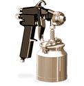
-
DESIGN & ENGINEERING
3D File creation, 3D Scanning and File Repair.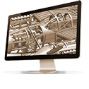
- Processes
-
SLA
Ideal for small or large, highly detailed show models and clear “lens like” parts.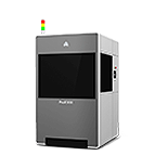
-
FDM
Real, durable, thermoplastics and single piece parts up to 36″ x 24″ x 36″.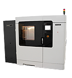
-
SLS
Perfect for producing large quantities, of small parts, in real thermoplastics.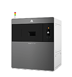
-
DLS/CLIP
High Resolution “injection molded like” properties. For parts up to: 3.2″ x 5.7″ x 12″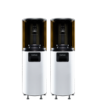
-
POLYJET
Speed, quality, fine feature detail and full color multi-durometer materials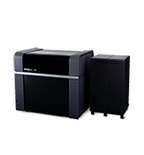
-
URETHANE CASTING
Castings using production grade materials, textures and color matching.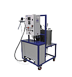
- Materials
-